01
Rock mass characterization
Know the rock mass before you advance Structures in the borehole, groundwater paths and subsurface anomalies to design ground support and anticipate water and voids.
Televiewer probes and log
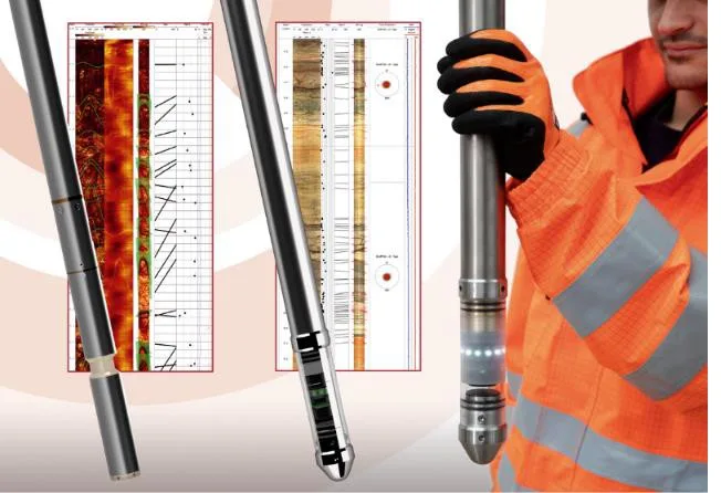
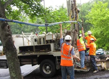
Optical and acoustic televiewer Proinfra service
Oriented log of the borehole wall to identify structures and their geometry.
Optical image Dry boreholes or boreholes with clear water. Shows texture, lithology and discontinuities.
Acoustic image Fluid-filled borehole. Records amplitude and travel time, even with limited optical visibility.
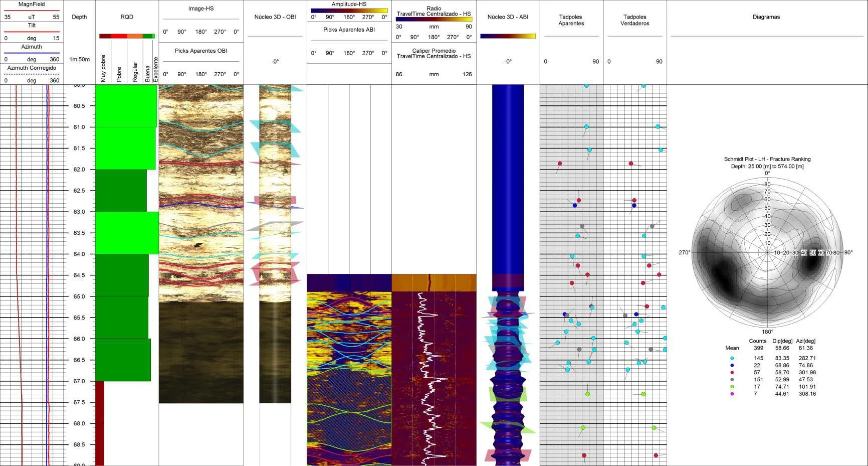
Deliverables Unwrapped image, structure picking, orientation and stereographic representation.
Structural interpretation of the borehole Correlated with geological mapping and core data to support the structural model and ground support design.
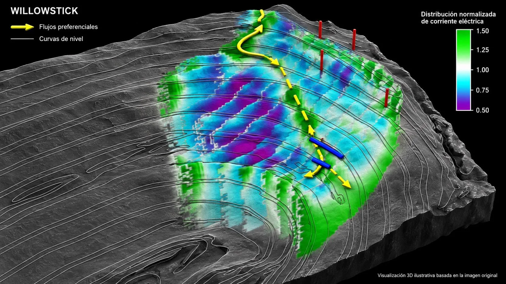
Groundwater flow mapping Electromagnetic method
Preferential water paths and conductive connections in 3D, with depth.
Flow path model Principle Injects alternating current and measures the magnetic field at the surface to model its distribution.
What it is for Direct drainage and grouting, and anticipate water before developing a drift.
Method track record More than 1,000 projects at mines, dams and tailings facilities.
Microseismic resonance · MSR Passive method
Detects subsurface contrasts without drilling.
What it investigates Voids, fractured or saturated zones and lithological changes, with depth estimates.
How it is used Prioritizes verification boreholes and complements flow mapping to locate water.
Timeframes Acquisition in days, interpretation in weeks.
Offered as a field and interpretation service. Anomalies are confirmed with geology and direct evidence.
02
3D capture · Geomechanical analysis
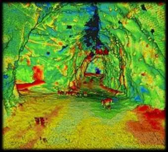
Measure the complete geometry of your workings Point clouds of kilometers of drifts, face meshes in minutes and automatic comparison for convergence and bolts.
Displacement measured by comparing scans
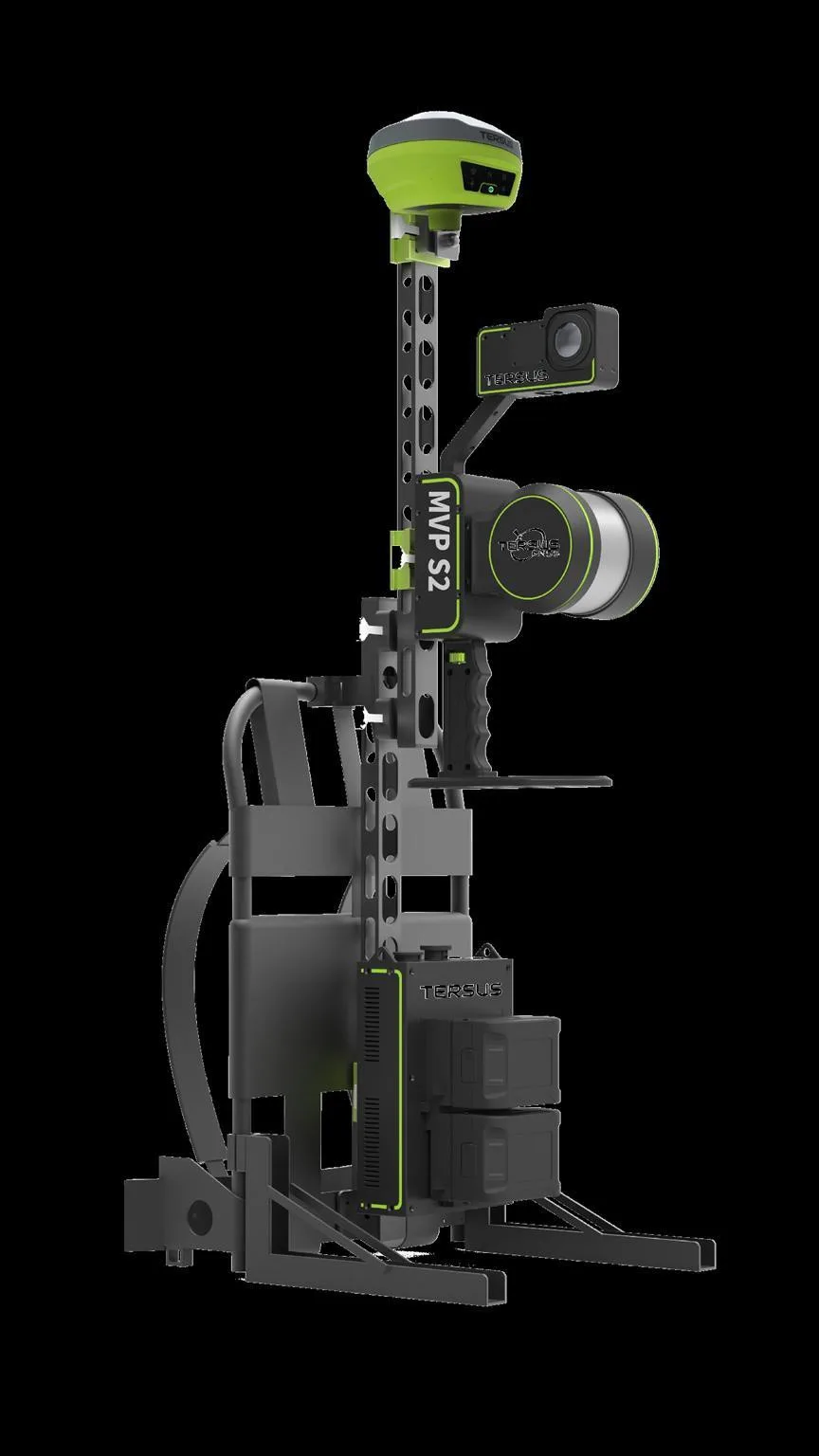
Mobile SLAM scanning Survey-grade LiDAR
Long traverses without drift, ready for geotechnical analysis.
>8 km Per scan, without drift
~1 cm Cloud-to-cloud registration
640,000 Points per second
< 24 h From scan to decision
Mobile SLAM scanner Operations Walked, driven or mounted; it does not require spheres or georeferencing each section.
Processing Local and with no per-scan cost. The same cloud feeds convergence, volumes and tracking of bolts, plates and shotcrete.
Specifications Range 0.5 to 120 m, 360° × 270° field of view, integrated RTK, 3 h per battery set, IP65. Exports LAS, LAZ, E57, PLY and PTS.
Options: equipment purchase with training, or scanning service by Proinfra.
Real-time face mapping LiDAR + HD imagery
The georeferenced face mesh replaces manual mapping under unsupported ground.
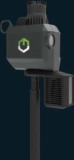
Face mapping equipment Scan LiDAR of the face and walls with onboard computing; 3D mesh ready in less than 10 minutes.
Image High-definition photography with LED lighting; the texture is projected onto the mesh.
Georeference and align Automatic referencing to the mine grid and alignment of successive scans.
3D face mesh with structures Structures Discontinuities, contacts and lithology changes to anticipate ground support.
Orientation Dip and azimuth measured on the mesh, without exposing the geologist.
RMR and RQD Calculated with georeferenced 3D data and exported to geotechnical software.
Exposure at the face reduced by more than 95%, according to the manufacturer. Option: annual license with a prior on-site evaluation.
Convergence and bolts, automated Cloud platform
Processes the LiDAR cloud without intervention and reports deformation and support in minutes.
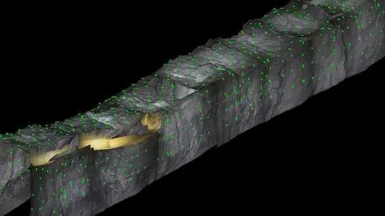
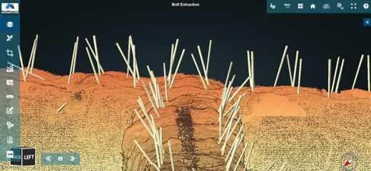
Bolts extracted from the cloud Convergence Compares each scan with the previous one, the earliest one and the design; classifies deformation by severity and volume.
Bolts and plates Detects and extracts bolts from the cloud and reports density, spacing and installation angle.
Kilometers, not points Complete mine sections with results in minutes; subscription per kilometer of drift.
Scan Weekly survey on foot or by vehicle; cloud registered and exported the same day. Analyze Comparison against the previous campaign and the design, bolt extraction and a report with the zones of greatest deformation. Decide Proinfra defines scanning frequency and support criteria with the mine and trains the geotechnical team.
03
Continuous monitoring
Track the roof and walls between inspections Remote readings of strata displacement and alerts with defined responsibilities.
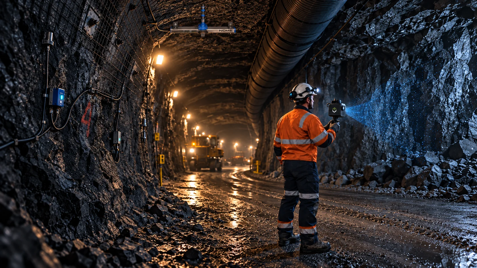
Monitoring network and operations center
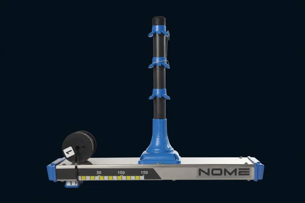
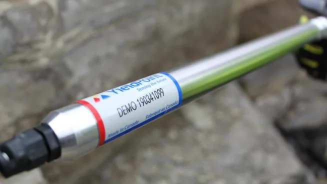
Digital telltale Strata displacement
Anchors at different depths to track movement of the roof or walls.
Digital telltale What it measures Displacement at up to four points in an instrumented borehole.
Where it is installed Critical areas of drifts and excavations, at positions defined by geotechnical engineering.
How it is interpreted The evolution of each point helps locate separation or deformation of strata.
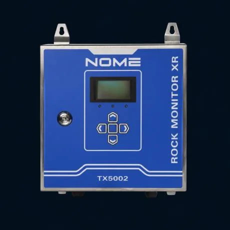
Controller and handheld reader Network operation
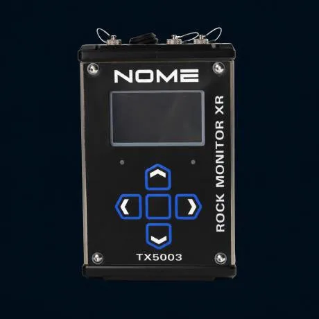
Two devices with different functions to operate and maintain the network.
Controller Handheld reader Controller Collects and stores network readings and transmits them to a PC or server on surface.
Handheld reader Battery-powered device for installation, configuration and maintenance, with data logging in the field.
Trends, thresholds and response Trigger action response plan (TARP)
An alert has operational value when there is a responsible person and a defined action.
Level Displacement Action Green < 5 mm Normal reading · weekly review Yellow 5–15 mm Notify geotechnical team · inspection within 24 h Red > 15 mm or accelerating Restrict access · reinforce support
Example values. Thresholds, recipients and actions are defined by the mine in its response plan.
04
Digital instrumentation
Measure internal deformation of the rock mass Extensometers and crack meters with digital readout and telemetry, according to the deformation mechanism and borehole conditions.
Field installation
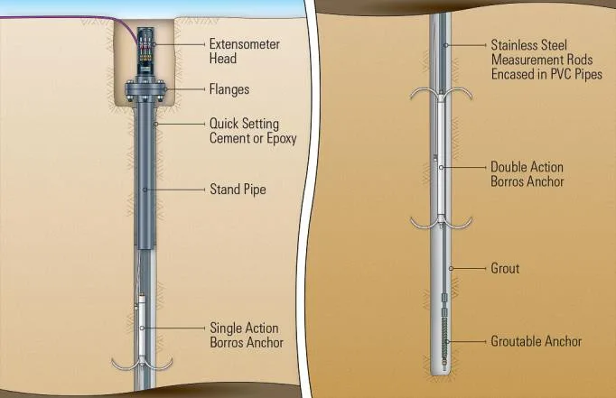
Ungrouted multipoint extensometer Soft rock
Spring anchors to observe internal deformation.
Multipoint extensometer Application Ungrouted boreholes, up to six points for soft rock.
Specifications 1 to 6 steel spring anchors · 38–50 mm borehole · digital readout in mm and °C · cable up to 500 m.
Digital crack meter Local opening
Fixed on both sides of a crack, it records changes in opening.
Application Track the local evolution of a discontinuity.
Specifications Digital readout of opening in mm and °C, compatible with data loggers and wireless telemetry.
Crack meter Distinguish movement within the rock mass from localized opening at a discontinuity.
Extensometers for hard rock Cabled · Bluetooth
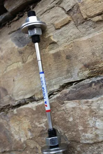
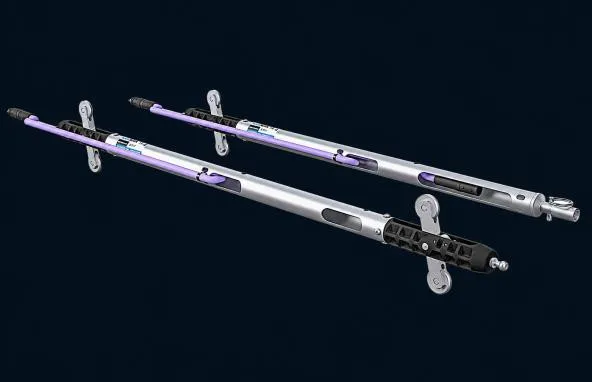
Locate the depth at which movement is concentrated.
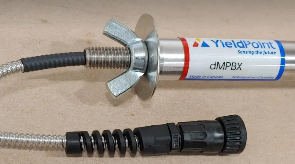
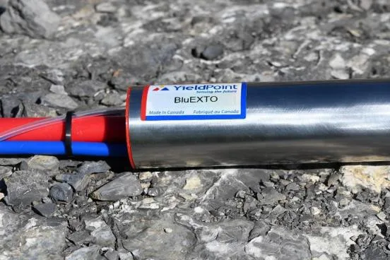
Grouted extensometer Extensometer with Bluetooth Grouted, cabled Up to six anchors, length up to 30 m, range of 125 to 250 mm, typical accuracy 0.5% FS and RS485 up to 500 m.
With integrated Bluetooth The same sensor with a data logger and Bluetooth 5 in the head; typical resolution 0.02% FS.
From instrument to data Acquisition and link
Acquisition combines compatible equipment with the coverage available in the mine.
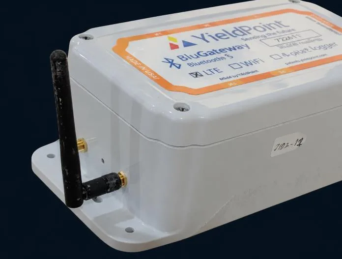
Gateway Field app Gateway Groups readings: RS485, Bluetooth 5 and vibrating wire depending on the model.
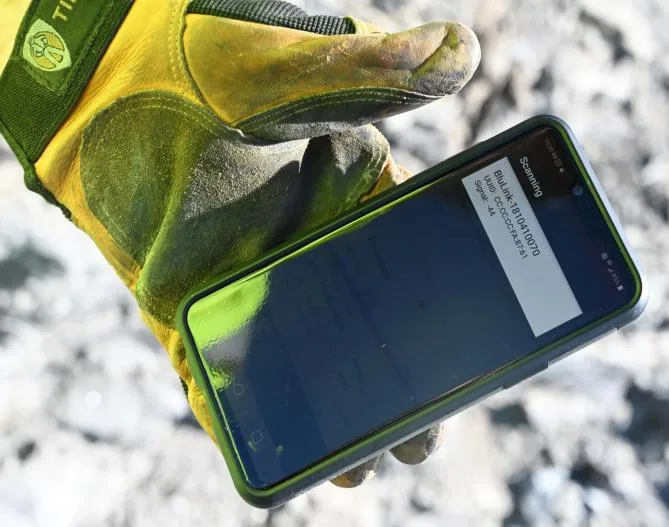
Field app Configuration and reading through a compatible Android device.
Link to platform Wi-Fi, Ethernet or LTE-M where coverage exists.
05
Vibrating wire instrumentation
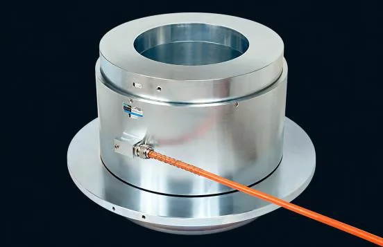
Evaluate displacement, water and support together Extensometers, convergence, tilt, pore pressure and load on support to verify the design.
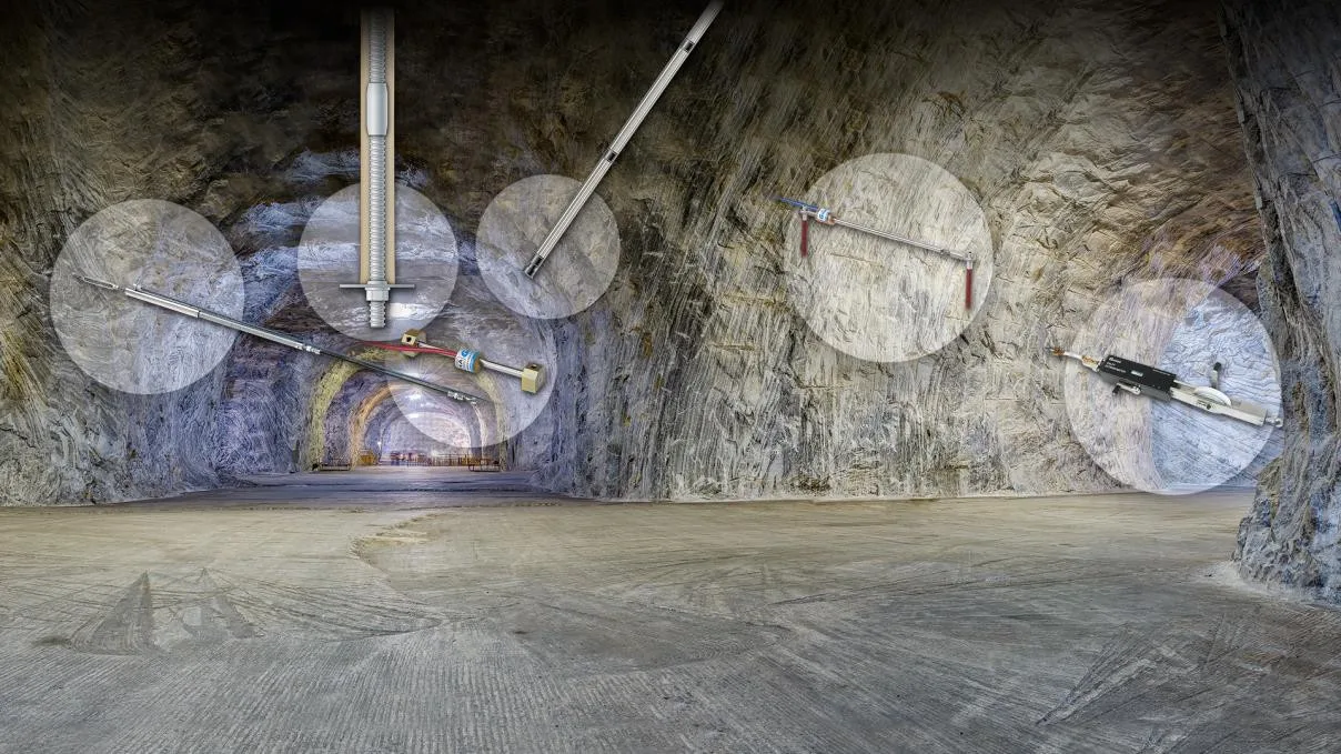
Instrumentation in an underground excavation
Multipoint extensometers Internal deformation
Relative displacement between anchors at different depths.
Multipoint extensometer · diagram Specifications Vibrating wire transducers, ranges from 12.5 to 300 mm, up to 6 anchors per borehole.
Convergence and tilt Closure of workings
Closure of an excavation and movement along a borehole.
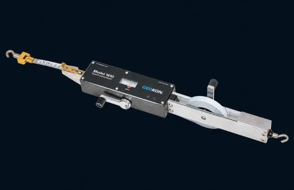
Tape extensometer In-place inclinometer chains Tape extensometer Changes in distance between opposite anchors. Tapes of 20, 30 and 50 m, accuracy ±0.1 mm.
In-place inclinometer chains MEMS sensors inside inclinometer casing, typical range ±15°, automated reading.
Water, load and pressure on support Pore pressure · load · total pressure
Each sensor records a different variable; interpreting them together provides context.
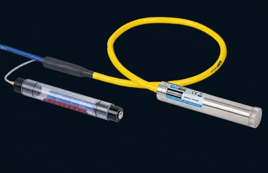
Piezometers Annular load cell Piezometers Pore pressure and response to drainage. Ranges from 70 kPa to 7 MPa, typical accuracy ±0.1% FS.
Load cells Force transmitted by anchors or support. Capacities from 200 to 2,000 kN.
Pressure cells Total pressure on a surface. Ranges from 350 kPa to 7 MPa, with integrated temperature.
06
Support
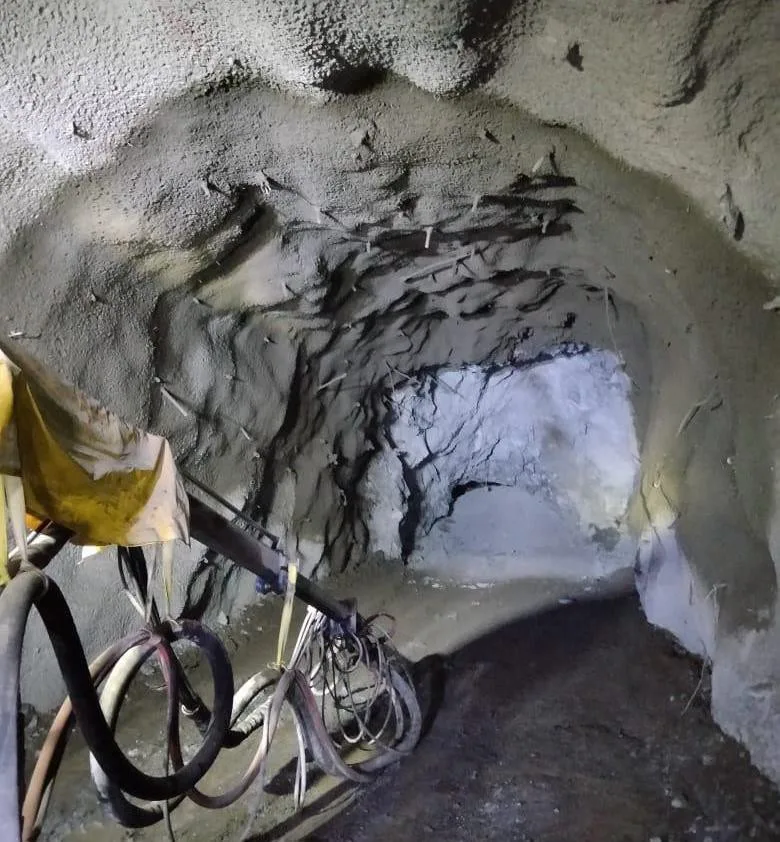
Better-performing shotcrete Admixtures for wet-mix and dry-mix shotcrete, and structural polypropylene fiber, with technical backing and local supply.
Shotcrete in a drift
Shotcrete admixtures Wet-mix and dry-mix
Complete line: accelerator, superplasticizer, water reducer and retarders.
Product Function Dose Alkali-free accelerator Very fast setting and rapid strength development 3 to 10 kg per 100 kg of cement Polycarboxylate superplasticizer High water reduction; up to 1 h of workability retention; tolerates excess fines 3 to 10 cc depending on w/c ratio Water reducer and retarder Greater resistance to clays; workability up to 3 h 7 to 11 cc Set retarders Control bleeding and improve pumpability 1 to 8 cc
Structural polypropylene fiber Replaces steel fiber
Less rebound, lower cost and validated energy absorption.
7:1 More fibers per kg than steel
30 % More efficient than other synthetics
1–5 kg/m³ Dosage
Less rebound Cost savings compared to steel fiber.
Validation In situ panel testing followed by energy absorption testing at IMCYC.
Supply Inventory in Mexico, 6 kg bags and a certificate for every batch.